Envelope detection is the final stage of our signal processing, the aim of this stage is to convert the pulses of 10-250Hz EMG signals into an envelope. In my previous post on rectifying I gave an image to describe what an envelope actually is, for the sake of simplicity I’ll reuse that image again which can be found below. The blue signal represents the pulses of EMG signals and the red signal represents the envelope that is to be produced.
Demonstration of signal envelopes.
A simple RC envelope detector could be used, however because the envelope will be attenuated at the output and gain would be needed it is more efficient to use an active envelope detector. This comes in the form of an op amp integrator. The integrator acts as a low pass filter, with a cut off frequency given by fc=1/(2*pi*R2*C) and a DC gain of -R2/R1. For our application the cut off frequency was set to approximately 2Hz and the DC gain was set approximately to 2x so the output envelope peak will be between 1V and 2V. The schematic for the circuit is shown below.
Schematic of the integrator / envelope detector circuit.
The circuit was simulated in NI Multisim. An input signal was generated by amplitude modulating a 100Hz carrier with a 2Hz data signal, this was then rectified so only the negative side of the signal passed through to the integrator. The output of the simulation is shown below. The input is the yellow signal and the output is the red signal. Notice how the output follows the envelope of the input and has a peak just above 1V. So in conclusion the circuit is working as we intended and we are now finished with the signal processing. Next is the last sub system of the project, the output.
Simulation of the Integrator / envelope detector. Yellow – Input, Red- Output
Once again ignore the title as it gives too much away, I should probably be more careful with my titles… Having filtered the signal we have now finished cleaning up and can begin to think about processing the signal. The final signal should have an amplitude that is proportional to the strength of the original signal, however rather than the exact value, which will oscillate like a sinusoidal frequency, a more useful measure would be the envelope of the EMG activity. This envelope can be then be input into a microcontroller for producing an output. Below is a plot demonstrating the concept of taking the envelope of the signal.
Demonstration of signal envelopes.
How can this envelope be produced then? A simple answer in our case, use an integrator circuit with a cut off frequency of ~2Hz. The input to the integrator needs to be a rectified form of the signal (This will be explained in the following post), ultimately either the negative or positive side of the signal can be used however for ease we will want a rectified signal that is always <0V. The reason for this is due to the fact that the integrator has a gain of -1. The output of the integrator is the input to the microcontroller and must be in the range of 0-3.3V hence the input of the integrator must be negative. Therefore the rectifier must output a negative signal.
But hang on… This post was titled ‘Precision Rectifier’ what’s with that? For a general large signal any electronic engineer could tell you that a rectifier can simply be a diode in series, however for small signals the voltage drop (usually about 0.7V) will distort the rectification process and in some cases completely block the signal, i.e. if the amplitude was always <0.7V. The EMG signal has been amplified however it is still a relatively low voltage and runs the risk of being block / distorted by a diode. Instead a precision rectifier is to be used as this circuit no longer suffers from the 0.7V voltage drop. The schematic of the precision rectifier is shown below.
Schematic of the precision rectifier.
A copy of the output from the precision rectifier is shown below. We can see from the simulation that the precision rectifier works as expected. Given the signal has been rectified the next step is to build the integrator and produce the envelope of the EMG activity.
Simulation of the precision rectifier. Red – Input, Blue – Output.
Having extracted the EMG signal and removed the common noise in the signals from the two electrodes, the next stage is to clean the signal further. From research it was found the frequency spectrum of EMG signals emitted from the bicep muscle are in a range of 10Hz to 250Hz with a peak at ~50Hz. For this reason any other frequencies outside of this range should be filtered out to further remove noise. This will be done using band pass filter with a lower cut off frequency of 10Hz and an upper cut off frequency of 250Hz.
The band pass filter is constructed using two second order filters; a Sallen-and-Key high pass filter and a Sallen-and-Key low pass filter. Both of these will have a quality factor Q=0.707. The schematic for the filter is found below, followed by the bode plot indicating cut off frequencies (-3dB frequencies).
Schematic of the band pass filter.Lower cut off frequencyUpper cut off frequency.
As can be seen from the bode plot the two -3dB frequencies are approximately at 10Hz and 250Hz. Now the signal has been cleaned up the next step is to rectify the signal, ready for envelope detection.
Now its time to choose an amplifier for our sensor. Unfortunately this post has been poorly titled, as it gives the game away a bit, do your best to ignore that. An amplifier needs to be used to boost our EMG signal to a useable level. However the type of amplifier needed must first be chosen, to decide we first look at the signal being received.
The sensor consists of three electrodes one attaches to a bony, EMG neutral, part of the body and the other two are placed along the contour of a muscle. You’re probably asking yourself why the two electrodes on the muscle, surely one will be enough? The answer to that question is noise reduction. The EMG signal produced by the body is greatly dampened by the time it reaches the surface of the skin and will only read approximately 2-3mVp-p, considering there will be thermal noise and noise from the surroundings the signal is likely to be lost in a sea of 5-10mVp-p of noise. To see how two electrodes help first consider a single electrode, we receive a noisy signal that contains the EMG signal no doubt it would prove incredibly hard to separate the two. Okay so lets try two electrodes, imagine the scenario where we place the two electrodes on exactly the same spot, both would have the exact same EMG signal and noise as a single electrode… Not very helpful at all. Picture now separating the two by a small distance, we can assume both would still pick up the same noise, however the EMG signal they pick up will be slightly different.
Consider this; when no activity is present both electrodes pick up the same noise (V1=N, V2=N), when activity is present the two electrodes read different EMG signals both hidden in the same noise (V1=A+N, V2=B+N). The sensor only needs to display muscle activity and so by taking the difference of these two signals, V1-V2, and assuming the noise picked up by the two electrodes are equal, we would arrive at a signal that is proportional to muscle activity and has a large reduction of noise V=A-B. Hence a difference amplifier with low common mode gain is wanted for this circuit.
The standard op amp difference amplifier is not sufficient for this sensor, an example, the low input resistance. Instead an instrumentation amplifier is more appropriate. As to why this is I would direct you to the Sedra & Smith Microelectronics book, specifically the chapter on difference amplifiers. It talks through the limitations of the differential amplifier and then explains the derivation of the instrumentation amplifier. I don’t mean to plug anything here, but if you’re an Electronic Engineer Undergraduate, you NEED that book!
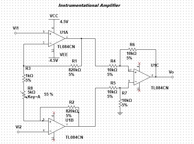
Bearing in mind the EMG signal will range from 2-3mVp-p, the differential gain will be set to ~1500. The gain will be variable to account for the unpredictable nature of the signals. The strength of the signals can change from person to person. The circuit is shown below:
Schematic for the instrumentation amplifier.
I won’t go through the derivation for this circuit as it is explained very well in the Sedra & Smith book. However it is not hard to see that the far right op amp is simply a differential amplifier with a gain of 1x, with two voltage buffers between the differential amplifier’s inputs and the sensor inputs.
Simulations where carried out in NI Multisim, first the differential mode. To test this Vi2 was grounded and Vi1 had a 1mVp sinusoidal signal input. As you can see Vo (Blue) was approximately 1.5Vp therefore the differential gain of approximately 1500 has been achieved.
Differential Mode Simulation: Red – Vi1 :: Blue – Vo
Next the common mode was to be tested. Both inputs had the same 1mVp sine wave applied to them. As you can see from below the output (Blue) was greatly attenuated to approximately 40uV.
In conclusion the instrumentation amplifier is working as expected, the next step is to filter the signal, removing any unwanted noise.
One of the first challenges to be tackled concerns the power supply. The device is to run off a single 9V battery, bearing in mind that the signals will be bipolar, this would require biasing for all amplifiers and filters. We are also only interested in the envelope of the signal and so only require one half of the wave (positive or negative side). All these constraints suggest the use of a dual rail supply, removing the need to bias op amps and allowing for a bipolar wave that can then easily be rectified.
To generate a dual rail supply from a single 9V battery a virtual ground is created. This is done using the following circuit, a virtual earth driver.
Converting the single rail supply to double rail.
As you can see from the simulation the circuit has created two voltages, referenced from the virtual ground, of +4.5V and -4.5V. Now the power supply has been sorted we can begin to retrieve the EMG signal from the muscles. The next stage is to design the input amplifier.